Radiography Testing
Radiographic Testing (RT) uses the short wavelength electromagnetic radiation passing through the material to detect discontinuities within the material. The radiation, which reaches the film after passing through the material, forms a shadow image on photographic film (radiograph). Areas of low absorption (slag, porosity) appear as dark areas on the developed film (radiograph). Areas of high absorption (dense inclusions) appear as light areas on the developed film.
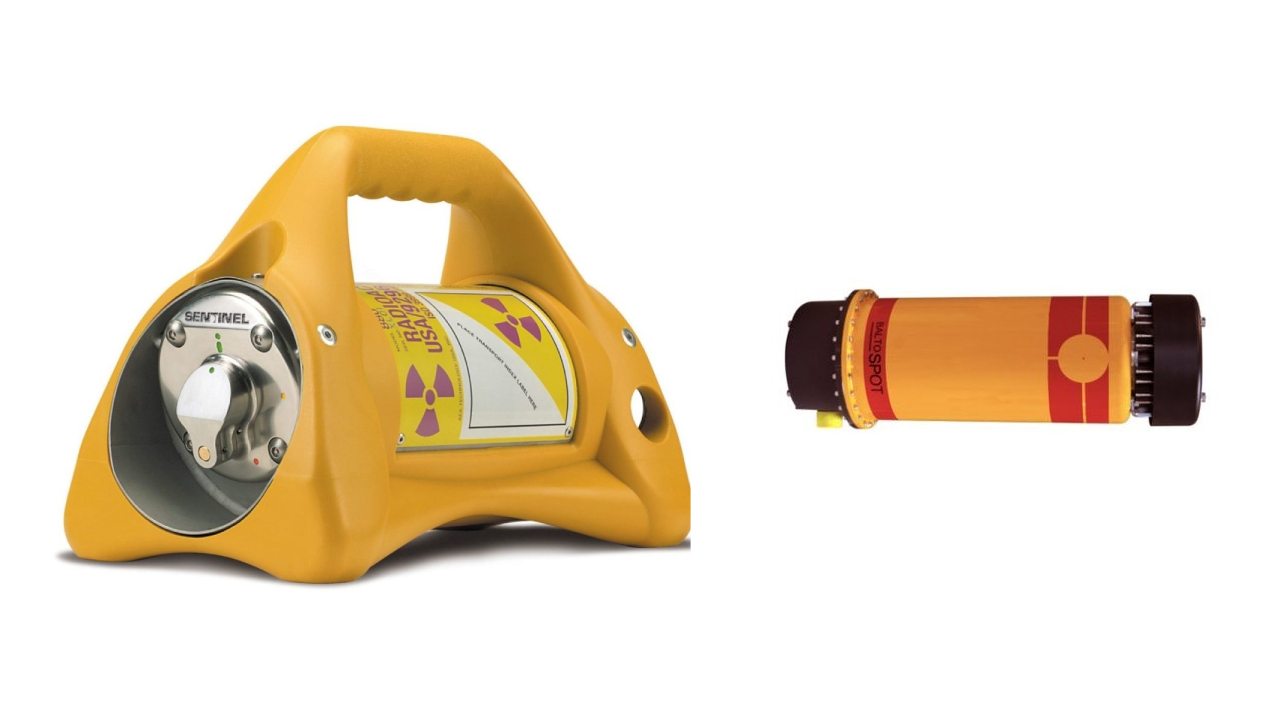
To perform industrial radiography, IXAR utilize various X-ray machines and radioactive isotopes to record internal discontinuities. IXAR is Equipped with the world’s-best X-Ray Crawler technology for 6” to 60” diameter pipeline radiography and has qualified and experienced personnel. IXAR offer the advantages of high radiography quality, high imaging sensitivity, low failure rate and high work efficiency.
In conventional radiography techniques, IXAR uses Iridium-192, Selenium 75, and Cobalt-60 isotope sources. IXAR also uses various high voltage X-ray machine up to 300 Kvp for filed radiography and up to 450 Kvp constant potential X-ray machines for fixed installation enclosure radiography.
Note: Add photographs of Some selenium camera, Cobalt camera and 450 Kvp Cp unit photographs. Remove Digitization of Radiographs and Close proximity radiograph from here.
DIGITIZATION OF FILM:
At IXAR, we understand your need to have proper storage and easy accessibility to obtaining the films. That’s why we make the most of the latest technologies to meet your requirements. With KODAK LS75 and LS85 High-Resolution Laser Film Digitizer, we deliver high performance, image quality and reliability. In the process, our experts capture film images, which are later converted to high-resolution digital images. All in all, it ensures a high degree of precision, excellent density resolution and precision, and spatial resolution.
CLOSE PROXIMITY RADIOGRAPHY:
With a restricted area of radiation, Close Proximity Radiography significantly reduces the radiation risk and eliminates the need to evacuate the work area. So, the testing doesn’t affect the production targets and daily work schedules. Apart from making the most of the latest technology and systems, our personnel utilize SELENIUM-75 radioactive isotopes to provide high-quality radiographs.
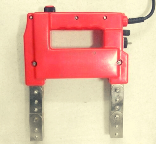
Magnetic Particle Testing
Magnetic particle Testing (MT) is used to locate surface and near surface discontinuities in ferromagnetic materials. Such discontinuities present in a magnetized part will cause a magnetic leakage field i.e. flux, to leave the part.
When magnetic particles are applied to this surface, they will be held in place by the flux leakage to give a visual indication. A magnetic particle test will be conducted by creating a magnetic field in a part and applying the magnetic particles to the test surface.
IXAR experts utilize Magnetic Particle Testing to detect surface and near-surface discontinuities and evaluate those discontinuities as per referencing standards or specifications for acceptability. It is fast and relatively easy to apply, and surface preparation is not as critical as compared to other NDT methods. We offer both on-site and in-house services as per your requirement.
IXAR uses YOKE, PROD, COIL and HEAD and TAIL shot type equipment to handle various forms of ferromagnetic components to fully satisfy the customer requirements. A versatile Universal Bench type equipment also installed at IXAR facility in Mumbai for bulk testing of small and medium size components. Note: Add photographs of Prod, Yoke, Coil and Universal bench type unit available in our IQM.
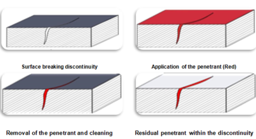
Liquid Penetrant Testing
Liquid Penetrant Testing (PT) reveals surface discontinuities in non-porous material and metallic and non-metallic surfaces by the “bleed-out” of penetrating medium against a contrasting background. This is done by applying a penetrant to the pre-cleaned surface to find discontinuities of the parts being inspected.
The penetrant is applied to the surface and allowed to remain on the surface for a prescribed time (penetrant dwell time); the penetrant liquid will be drawn into the surface opening of the discontinuities by capillary action. Following the removal of the excess penetrant, an application of the developer reverses the capillary action and draws the penetrant from the discontinuities. The resultant indications reveal the presence of the flaw so that it can be visually inspected and evaluated.
Materials that can be inspected using PT include: metals (aluminium, copper, steel etc.), rubber, glass, and plastics. The PT is used only to detect discontinuities open to the surface of the part being tested. IXAR qualified PT personnel generally uses Penetrant test to find discontinuities such as-
- Fatigue Cracks
- Grinding Cracks
- Porosity
- Laps
- Seams
- Pin holes in welds
- Lack of fusion along the edge of the bond line
Through this technique, IXAR experts evaluate the condition and quality of a component. In general, IXAR experts uses Solvent removable penetrant testing technique using Colour contrast and fluorescent penetrant materials for both field and workshop-based components. When required IXAR experts can carry out penetrant testing using Water washable and Post emulsifiable penetrant system. IXAR has facilities and personnel for high-volume processing of many different parts with both fluorescent and visible dye penetrants. Add photographs Filed penetrant kits. UV lamps, UV meter etc. related to PT.
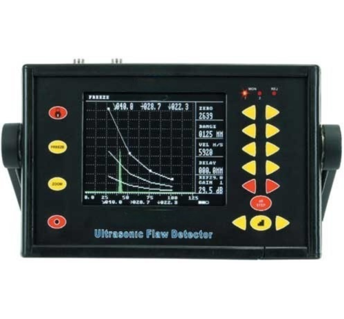
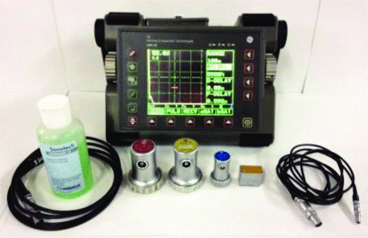
Ultrasonic Testing
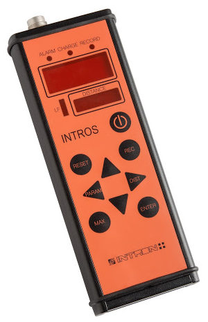
Ultrasonic Testing (UT) uses high-frequency sound waves (ultrasound) that are in the range of 500 KHz to 20 MHz to measure geometric and physical properties of materials, and detection evaluation of discontinuities within the materials. Ultrasound travels through different materials at different velocity. The velocity of sound propagation in a given material is constant. IXAR qualified technicians make uses this quick, non-intrusive and cost-effective testing technique to find discontinuities in plates, pipes, forgings and welds. This technique is highly reliable to find cracks and other planar discontinuities oriented in various directions within the materials. IXAR has various advanced Ultrasonic flaw detectors, Digital read out thickness meters. IXAR personnel are carrying out Ultrasonic flaw detection using Modsonic TFT-II, Modsonic DGS, Arjun 20, GE USM 35 & GE USM 36.
Ultrasonic Thickness Measurement
The use of Ultrasonic non-destructive testing (NDT) is used to measure the thickness of materials in all facets of the industry. The ability to gauge the thickness measurement of material without access to both sides of the test piece offers this technology a multitude of possible applications.
Ultrasonic thickness gauge can be set up for metals, plastics, composites, fibreglass, ceramics & glass. It is completely non-destructive with no cutting or sectioning required.
Ultrasonic thickness measurement is done by gages by precisely measuring how long it takes for a sound pulse that has been generated by a small probe called Ultrasonic Transducer to travel through a test piece & reflect back from the inside surface or for the wall.
Measurement is made from one side in “Pulse/echo” mode because sound waves reflect from boundaries between dissimilar metals. Ultrasonic thickness measurement is performed for the measurement of the thickness of Hot Metals, through coating and scale measurement of the inner surface of the pipe.
1) Measurement of Thickness through Hot Metals:
The thickness of the part can be measured in case of surface temperature reaches to 5000C. Particularly in metal, there may be instances when the thickness of the part needs to be measured during the ongoing process where the test piece cannot be cooled down.
Measurement of thickness is performed on one side of the part same as the measurement at normal temperature except the use of special probes and cooling techniques suitable for such high temperature.
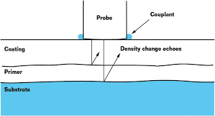
2) Measurement of Thickness through Coat/Paints:
The petrochemical industry used a network of pipes to transfer liquid and gases. These pipes are chemically coated or painted for their safety from any hazardous effects. Change in the thickness of the pipe affects its transmission capacity as well as overall performance.
Hence it is necessary to measure the remaining thickness of a metal pipe or any other metal in the industry subject to corrosion through one or more coats of paints or similar non-metallic coatings. This presence of paint or similar coatings will cause measurement errors with conventional ultrasonic thickness gages.
The paint has a much slower sound velocity. Such measurement of the thickness of coated metal can be done in two ways; Echo-to-Echo measurement and THRU-COAT measurement.
Echo-to-Echo thickness measurement involves the technique of timing the interval between two successive back wall echoes that represent successive round trips of the sound wave through the test material. In painted metal, these multiple back wall echoes occur only within the metal, not in the coating, so the interval between any pair of them (back wall echo 1 to 2, back wall echo 2 to 3 etc.) represents metal thickness only with the coating thickness cancelled out.
THRU-COAT measurement was used to identify the time interval represented by one round trip in the coating. That time interval is used to calculate and display the coating thickness, and by subtracting that interval from the total measurement the gage can also calculate and display the metal substrate thickness.
The equipment used for Through Coat & High Temperature (Up to 500 C) thickness measurement are,
Olympus 45 MG, Olympus 38 DL Plus, Olympus 39 DL Plus, Cygnus-, Cygnus 4 and Cygnus plus.
3) Measurement of Scale Thickness:
The formation of scale on the inner surface of pipes has become a major problem for various industrial plants because it may lead to large production losses. In the electric utility industry, a metallurgical technique for measuring thickness is employed to predict the remaining life of high-pressure boiler pipes. The metallurgical technique provides a very accurate measure of scale thickness.
Disadvantages of metallurgical measurement;
1) Such examination requires physical removal and replacement of pipe sections.
2) Overall procedure is time-consuming and expensive as it is directly related to downtime.
Ultrasonic techniques are used in the inspection of pipes to detect surface and sub-surface flaws and for measuring the thickness of material or distance to a flaw. This technique can also be used to quantify the amount of scale on the inner surface of pipes.
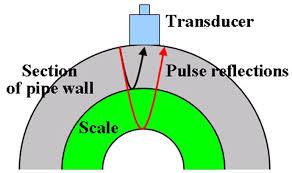
In this technique, an ultrasonic transducer on the outer surface of the pipe transmits and receives ultrasonic energy at its resonance frequency. The ultrasonic energy from the transducer enters the pipe and travels until it reaches the inner surface of the empty pipe where it is mostly reflected back toward the transducer.
When the scale is present on the inner surface of the pipe, some of this energy is not reflected back, but rather is transmitted into the scale. The acoustic impedance mismatch between the pipe and the scale causes the ultrasonic energy to be reflected. The amplitude of the reflected signal is associated with the impedance ratio between the two materials. It increases with a greater impedance ratio. Similarly, a reflection occurs at the interface of the scale and the fluid within the pipe.
The time of flight (roundtrip time) of a pulse within the scale can be determined by measuring the times of flight to the pipe/scale and the scale/fluid interfaces.
Helium Leak Testing
Helium Leak Testing (HLT) is based on the principle of field mass spectrometer. The leaked Helium gas is ionized by the electron beam from the filament within the ion chamber of the analyzing tube. The ions are accelerated using added voltage and move out through a slit and then passed through the magnetic field generated by the analyzer.
Since the circular trajectories of the ions depend on their mass, the collector can catch only the helium ions and detect helium. Using a special detector the ion current is converted into an electric current. This current is accelerated and displayed on the screen using leak detection units. The measured current is in direct proportion to helium concentration and therefore equal to the measured leak.
The HLT is a system containing the following modules;
a) Helium mass spectrometer leak detector.
b) Control system and valves which control individual steps of the measuring cycle, from evacuation to testing to venting.
c) Rotary & TMP vacuum pumps to maintain sufficiently low pressure in the spectrometer
d) Fixture, which connects the unit to be tested with the detector.
At IXAR, we specialize in Helium Leak Testing, which is a very sensitive and quantifiable test. It is reliable and best-suited to be integrated into the manufacturing process. IXAR personnel ensure that this highly sensitive and technical method is robust and works efficiently as part of a production line.
Wire Rope Testing
A large number of ferrous steel wire ropes are in use in different industries. Premature discard and replacement with the new rope involve in unreasonable costs while operating the rope, which already reached discard criteria, is dangerous.
Visual inspection is obvious, but only visual examination is not sufficient due to the specific rope design. Non-destructive magnetic inspection of ropes enables to gather of comprehensive data for making a reasoned decision. Magnetic flux leakage (MFL) equipment with strong magnetization can inspect ropes reliably, and smart software facilitates data interpretation.
Our professionals test the condition and estimate the remaining service life of a wire rope through Wire Rope Testing. We start with monitoring the wire rope’s production process, then determine the parameters by load tests in our workshops and extend to the non-destructive testing of installed wire ropes.
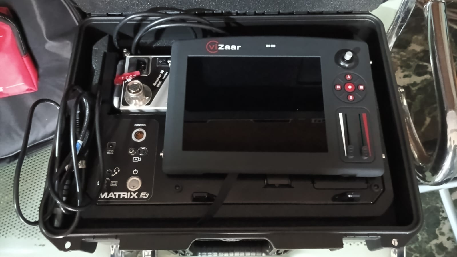
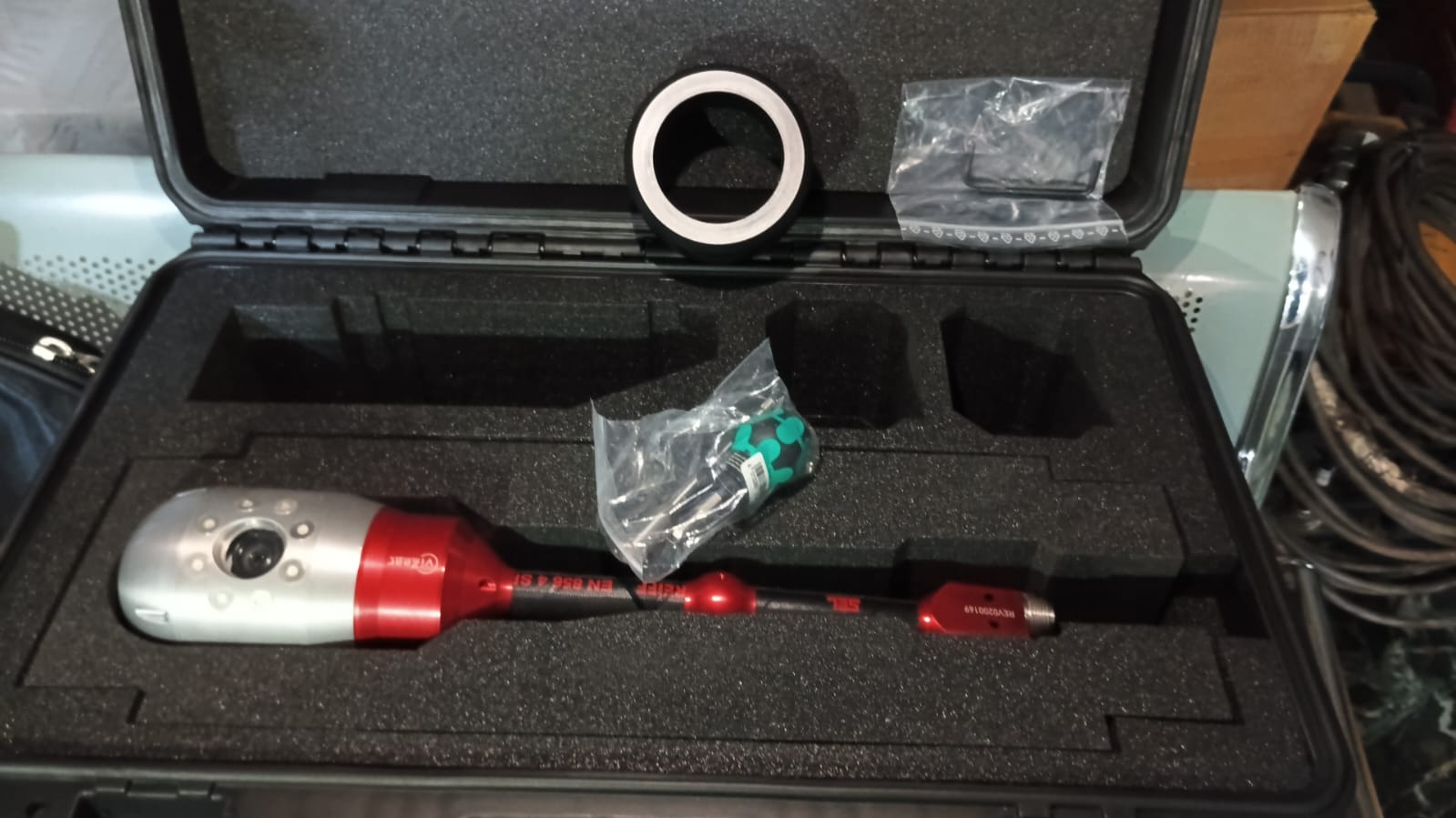
Visual Inspection
Visual Inspection Services (VI) is one of the oldest and primary Non-destructive Testing among all. It is simple, easy to apply, quickly carried out and charges a very low cost. Even though a component is to be inspected using other NDT methods, the visual test can reveal gross surface defects that lead to immediate rejection of components. The presence of finer defects is of utmost importance with a very high degree of precision.
The benefits of Visual Inspection Services are
1) Quality control and assurance
2) Knowledge data acquisition and analysis
3) Early detection of defective parts hence saving costly field repair
4) Demonstrating high-quality standards
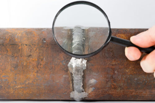
IXAR has expertise in performing Visual Inspection with the help of a boroscope and other devices such as filet weld gauges, undercut gauges, flashlight, ruler as well as a magnifying glass in order to determine various lengths, measurements and quality of welded parts and components to verify that products meet the requirements of the specifications. IXAR offer visual inspection in the Oil & Gas industries, aerospace and automotive sectors.