Phased Array Ultrasonic Testing (PAUT)
The principle of constructive and destructive interaction of waves was first demonstrated by English scientist Thomas Young in 1801 in a notable experiment that utilized a two-point source of light to create an interference pattern. Waves that combine in phase reinforce each other, while the waves that combine out-of-phase will cancel each other. Phase shifting or phasing is in turn a way of controlling these interactions by time-shifting wavefronts that originate from two or more sources. It can be used to bend, steer or focus the energy of the wavefront.
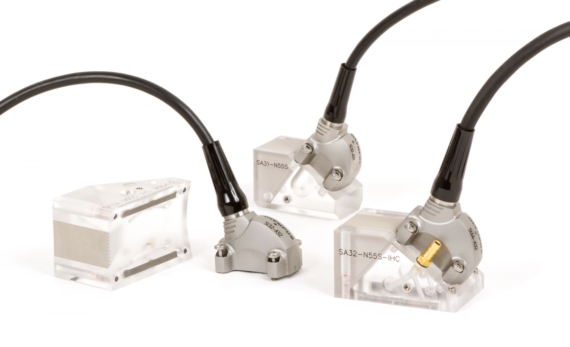
PAUT PROBES WITH WEDGES
Phased Array Ultrasonic Testing System utilized multiple point source transducers that were pulsed so as to direct the sound beam of this controlled interference pattern. An array transducer contains a number of separate elements in a single housing, and phasing refers to how these elements are sequentially pulsed. A phased array system is around a specialized ultrasonic transducer that contains many individual elements (typically from 16 to 256) that can be pulsed separately in a programmed pattern.
These transducers are used with various types of wedges, in contact mode or in immersion testing. Their shape may be square, rectangular or round and test frequencies are in the range of 1 to 10 MHz. The phased array technique has many potential applications, but can be inhibited by limitations such as geometry, time and access.
Depending upon client needs, IXAR has capabilities to deliver the following expertise;
1) Perform encoded scans on complex geometries.
2) Individual tailor development of qualification blocks, configuring rigs for data collection and levels of post-analysis reporting.
3) Inspection of small bore tubes- internal diameter of 50mm down to 6mm.
4) Inspection of complex geometry branch welds with variable weld profiles using encoded scanning for accurate sizing of internal defects.
5) Corrosion of inspection of Storage Tanks.
6) In-situ inspection of transverse cracks along shafts and axles for the public transport
7) Provide accurate analysis and reporting on the presence of cracks to establish the client to make an informed decision for repair and continued operation.
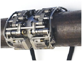
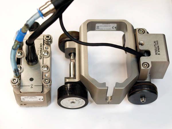
COBRA SCANNER
7.5MHZ – 16Elements Probe With Wedge from 0.84” TO 4.5” OD [Small Dia] & Thickness from 4mm
 SCANNER WITH PROBE FITTINGS
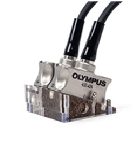
DUAL MATRIX PAUT PROBES TO TEST CORSE GRAIN MATERIAL [SS, INCONEL WELDS]
Through a team of trained, skilled and experienced professionals, IXAR provides advanced Phased Array Ultrasonic Testing (PAUT) for flaw detection, sizing and imaging. It offers significant technical advantages for weld testing and plant monitoring over conventional ultrasonic as the phased array beams can be steered, scanned, swept and focused electronically from a fixed probe position.
DMA PROBE FOR SS, INCONEL , COARSE GAIN MATERIAL TESTING
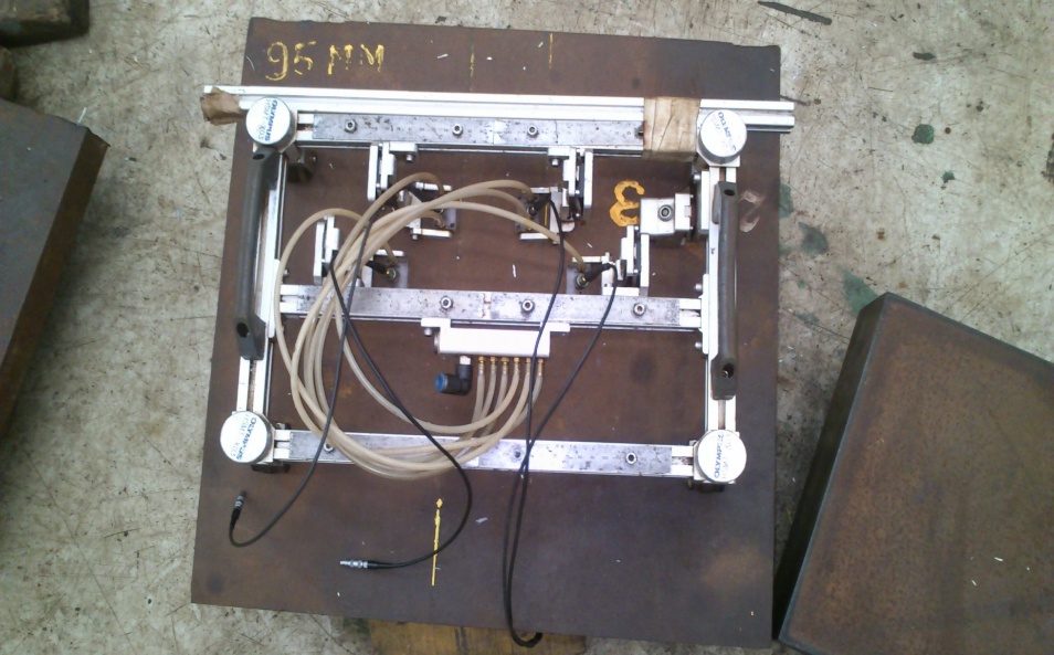
HYDROFOAM PHASED ARRAY SET UP FPR CORROSION TESTING
IXAR has expertise in PAUT in the following fields;
a) In the testing of highly attenuated Stainless Steel & Inconel Welds
b) Small diameter pipe welds from Diameter from 0.84″ (21.34mm) to 4.5″ (114.3mm).
c) Pressure vessels, Boilers, Heat Exchangers, Columns, Tanks etc.
d) Corrosion Testing of Vessels, Tanks & Pipes.
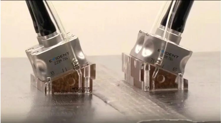
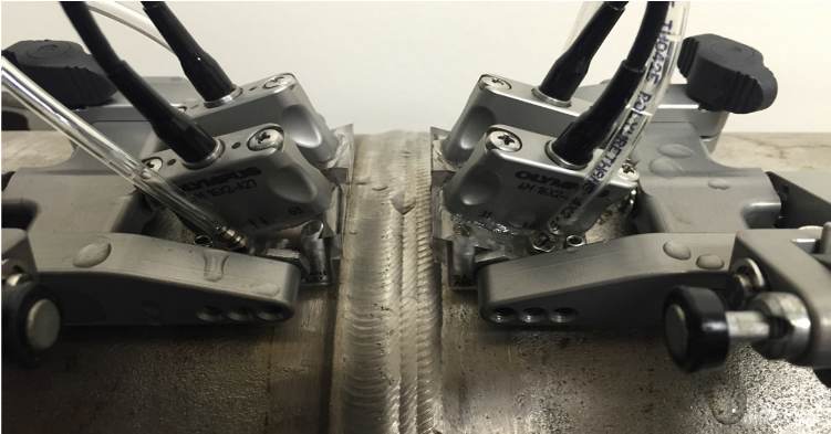
Time of Flight Diffraction (TOFD)
Time of Flight Diffraction is used for a variety of applications, being the primary use is rapid weld testing of circumferential and axial weld seams, also known as perpendicular TOFD scanning.
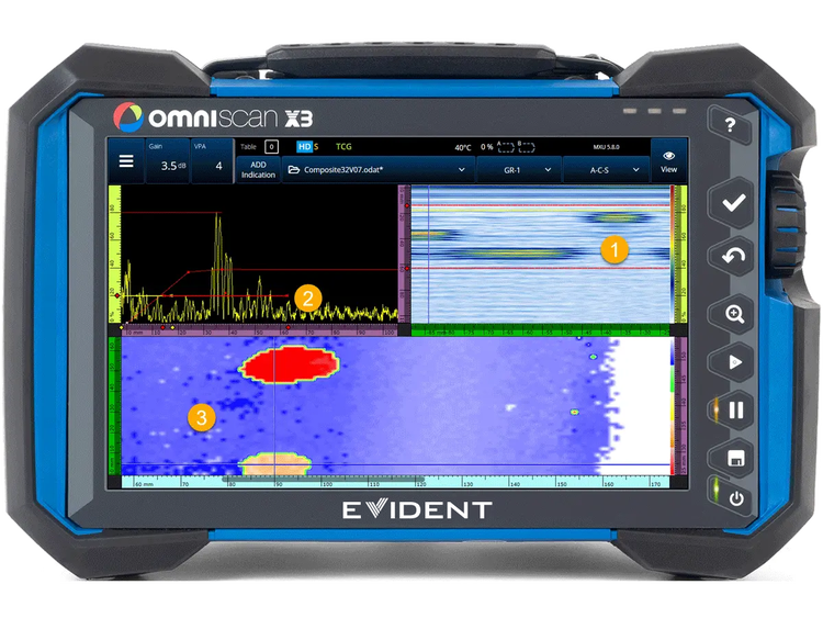
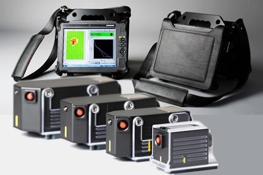
PAUT & TOFD Equipment with display of Data Captured
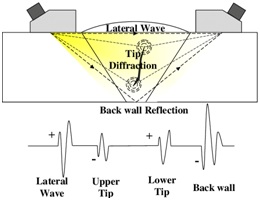
TOFD is performed using longitudinal waves as the primary detection method through the ultrasonic sensors that are placed on each side of the weld. One sensor sends the ultrasonic beam into the material and the other sensor receives reflected and diffracted ultrasound from anomalies and geometric reflectors.
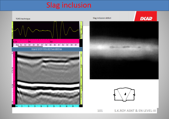
TYPICAL DISPLAY OF SLAG INCLUSION IN TOFD & RT IMAGE
Using ultrasonic beam spread, TOFD provides a wide area of coverage for anomaly detection in the material being tested. When the beam comes in contact with a tip of a flaw, or crack, diffracted energy is cast in all directions. Measurements of the time of flight of this diffracted beam enable accurate and reliable flaw detection and sizing.This is the case even if the crack is not oriented to the initial beam direction.
During typical TOFD inspections, A-Scan is collected and used to create B-Scan (Side View) images of the weld. Post-acquisition analysis is done using software to measure the flaw length and through-wall height.
IXAR professionals are highly trained and experienced in TOFD ultrasonic testing for various core industrial sectors. Our expertise in using state-of-the-art equipment such as Omniscan has allowed us to perform specific testing in:
a) Inspection of high-pressure and high-temperature pipe welds on circumferential and longitudinal seams weld about 20 mm.
b) Sizing of known defects has been performed all around the country on pipeline welding, and high-pressure vessels. A generated analysis report outlining the sizing of defects can be provided to the client for their reference.
Automated Ultrasonic Testing (AUT)
Automated Ultrasonic Testing (AUT) was developed for the fast and reliable inspection of girth welds during the construction of long-distance pipelines, both on and offshore. The system is characterized by high inspection speed and instantaneous recording of results.
Unlike radiography, it provides immediate feedback on weld conditions. The capability of AUT to characterize and size flaws enables the application of Engineering Critical Assessment-based acceptance criteria for weld imperfections.
AUT uses mechanized scanners that are computer controlled to move the transducers over the surface of the material being inspected. As the transducer moves, the computerized system acquires ultrasonic inspection data on a predefined grid, often acquiring data from a number of different transducers at one time.
The data is then displayed within the computerized interface, allowing the operator to manipulate it to provide the data displays that shows the areas of interest within the inspection volume. AUT can utilize any ultrasonic transducers or any combination of these. AUT can be used for newly fabricated welds in lieu of radiography, and also for in-service inspection to detect and trend flaws.
Automated UT (AUT) gives pipeline construction projects many advantages including;
1) High-Speed Inspection (as motorized) & immediate weld scan result
2) As this method is acceptable in lieu of RT by all International codes & standards. There are no safety issues with respect to radiation exposures.
3) No interruption to other workers.
4) More accurate inspection results.
5) Reduction of overall project cost.
6) All inspection results are electronic, reducing the cost compared to radiography techniques.
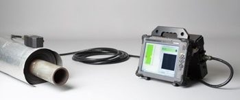
We perform Automated Ultrasonic Inspection with one of the most advanced machines in the world called UT Scan
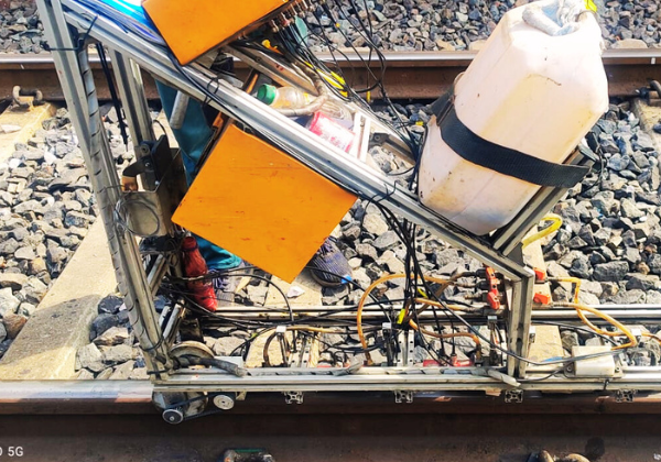
USFD For Railways
Although there is a boom in the automotive and aviation industries, railroads are still paving the way significantly for the purpose of transportation. Indian Railway accounts for the fourth largest railway network in the world by size, with a route length about 67,000km. Also, 95% of all the routes are electrified with 25kV, 50Hz AC Electric traction.
Every millimetre of those rail tracks needs to be kept in safe conditions in order to ensure the safety of thousands of passengers and crew members who ride abroad every day. These rail tracks are built across different locations where we find extreme weather temperatures as well as continuous rail transport. Due to these conditions, developing flaw inside rail tracks is an obvious phenomenon which leads to the weakening of the track and weld area.
The most common cause of rail failure is fatigue fracture, which is due to imperfections present in the material or due to crack formation during services. Thus the successful performance of rails is defined by their resistance to crack formation and crack propagation. Hence it is essential to identify and locate these cracks and flaws in rail and weld by taking corrective actions such as servicing them with ultrasonic detection technology.
IXAR has been practising Ultrasonic Flaw Detection for many years and become a leader in India. IXAR started its USFD for Railways in January 2018 by deploying experts in Ultrasonic Testing. Currently, IXAR has 35 RDSO-approved operators with 1 QAP Head and 4 technical executives to handle all the operations. To date, IXAR has completed more than 10 projects of Ultrasonic Flaw Detection of Rail Tracks at Ahmednagar, Jaipur, East Coast Railway ,Lucknow, Varanasi ,Chennai and Kolkata.
The RDSO-approved ultrasonic flaw detectors used for this purpose are MODSONIC Einstein-II AT, MODSONIC RAILSCAN-120 , EECI-DS-322 AT and EECI – MULTISCAN SR09
Pulse Eddy Current Testing (PECT)
Pulse Eddy Current Testing Services (PECT) is a technique used for corrosion under insulation (CUI) screening on carbon steel structures such as pipes, vessels, tanks and spherical tank legs without the need for contact with the steel surface.
PECT is a static technique able to measure spot percentage variations in steel thickness through any non-destructive and non-magnetic material between the sensor and steel surface such as air, insulation material, concrete, plastic coatings, paint, seawater, marine growth, deposits, oil etc. PECT is a comparative technique where the percentage variations measured on the specimen are compared with a calibration value which is assumed to be the full wall thickness.
The PECT measurements can be split into two phases. In the first phase, a current applied to the transmitter coil generates a magnetic field around the probe known as the ‘primary field’. The primary field is unaffected by the presence of any non-conducting and non-magnetic materials and penetrates undisturbed through the coating to reach the steel surface below.
In this way, the carbon steel directly beneath the transmitter coils is magnetized. Since carbon steel is ferromagnetic (i.e. it has a high relative magnetic permeability), only the top layer of the steel is magnetized.
In the second phase of the measurement, the current in the transmitter coils is switched off and as a consequence, the primary magnetic field collapse. The changing magnetic field induces electrical eddy currents in the surface of the steel material and these eddy currents generate a secondary magnetic field that reaches the receiver coils of the PEC probe inducing a voltage to this. The magnitude of this voltage as a function of time is referred to as the ‘PEC signal’.
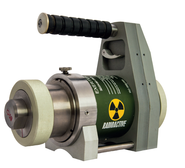
Close Proximity Radiography (CPR)
Close Proximity radiography (CPR), also known as Small Controlled Area Radiography (SCAR) is a technique used to perform radiographic examination with minimal disruption to surrounding activities. It allows for radiographic testing to be conducted closer to personnel and ongoing work, by utilizing specialized equipment and shielding to minimize radiation exposure.
- CPR is a method of industrial radiography that focuses on reducing the size of the controlled area needed during Radiographic Examination.
- CPR employs specific collimation and shielding techniques to minimize radiation scatter and limit exposure to safe levels at a desired barrier distance.
- CPR allows for radiographic testing to be performed while other operations continue nearby, minimizing downtime and disruption.
- CPR utilizes shielded containers for radiation sources (often a low-energy isotope like Selenium-75) and collimated exposure heads to direct the radiation beam.
- CPR utilizes Flexible shielding materials and sometimes shielding blocks to reduce radiation levels and allow for radiography near radiation-sensitive equipment.
- Personnel working with CPR are qualified and monitored, and barriers are set at reduced distances, often as close as three meters.
- By minimizing the controlled area, CPR allows other work activities can continue without interruption during the radiographic inspection.
- Reduced Downtime, lower project cost, improved safety, greater flexibility, enhanced image quality and the benefits of CPR when compared to conventional Radiography.
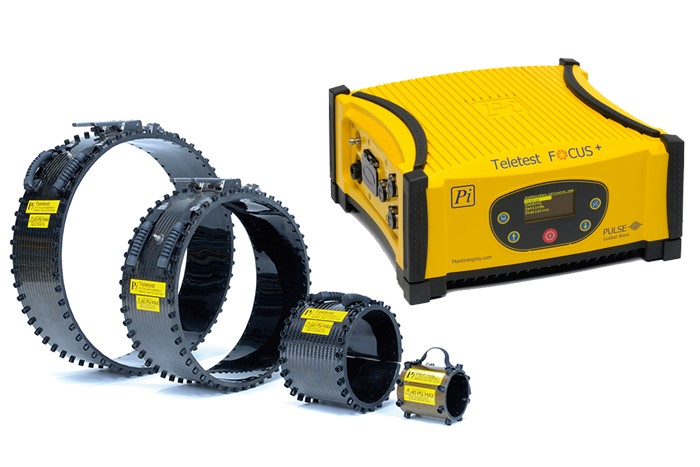
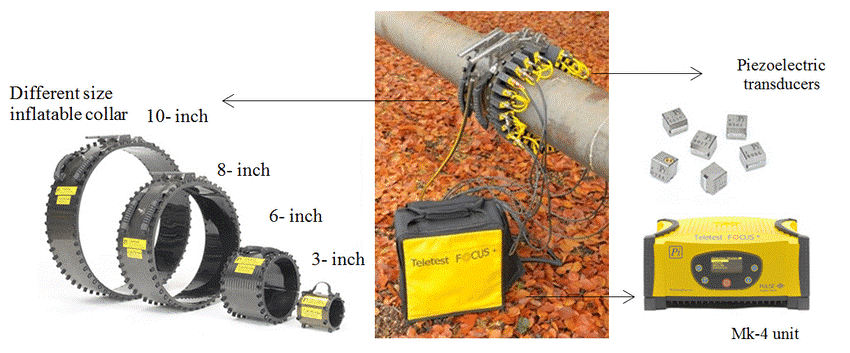
Long Range Ultrasonic Testing (LRUT)
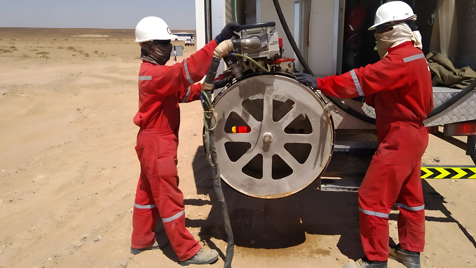
Long Range Ultrasonic Testing (LRUT), also known as guided wave ultrasonic testing is a fast and cost-effective method for inspecting long lengths of pipes. The technology is operated by placement of an array of probes (transducers) placed in the belt, circumferential wrapped around the pipe being inspected. The transducer then generates and receives low-frequency ultrasonic-guided waves longitudinally down the length of the pipe.
The returning echoes indicate discontinuities such as corrosion and other abnormalities. Distance covered by the ultrasonic waves is dependent on a number of factors related to pipe coating, branch connections, and fittings and above-ground or buried locations. The system can inspect both directions from each inspection location and therefore can maximize production.
The benefits of LRUT are;
1) Screening long lengths of pipes at one time.
2) Inspection of 100% of pipe.
3) Detection of corrosion and erosion under the insulation of pipes.
4) Analysis of pipes at different access locations such as wall, road crossing and buried sites.
5) Screening of on and offshore pipework, even in tightly packed racks.
6) Riser Inspection.
By choosing IXAR for your long-range ultrasonic testing, you will receive 100% quality assurance that your maintenance schedule will be met and you will be benefited from our in-depth knowledge of surveying pipelines and detecting discontinuities. Based on our reports, you will be in a position to make decisions regarding pipeline asset management.
Digital / Computed Radiography
IXAR has invested in emerging technology in the field of NDT which is Computed Radiography, which enables the digital capture of an image by use of a re-usable imaging plate (IP) which is coated with a phosphor layer, and when exposed to radiation is able to store resultant energy.
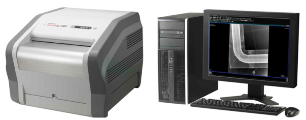
The IP is then scanned using a laser scanner which results in the stored energy being released as ultraviolet light, the intensity related to the amount of radiation received, these light intensities are then read by a laser and a digital image is generated. This image is stored as raw data, and although the image can be enhanced to optimize the contrast, magnify and measure the component the initial image remains unchanged.
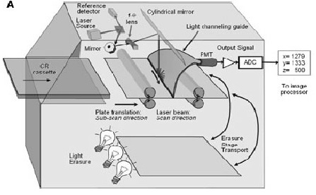
Computed Radiography Diagram
Computed Radiography has many advantages over conventional radiography such as –
1) No expensive films to purchase
2) Quick results without processing of chemicals (more environmentally friendly)
3) Wider latitude to enable a greater thickness range to be captured on one exposure
4) Sharing of images electronically and easier storage (enhanced archiving and retrieval)